This year I played in Defcon Quals with a small team. We did not qualify but it was still quite fun. Generally the challenges were of pretty high quality and were really interesting, so kudos to Nautilus Institute for pulling off a great CTF!
I personally ended up solving one reversing challenge during the CTF (kkkkklik) and finished Opacity a little bit after the end of the CTF. I was extremely close on the solution but unfortunately due to tiredness I had made some small mistakes and couldn't figure out how to correctly complete the challenge. That said, this is an extremely cool challenge and deserves a writeup!
TLDR: :explodingdog:
Without further ado...
Challenge Handout
Challenge Description
We purchased this small IC fabrication shop but can't seem to make heads or tails of what kinds of chips it's actually producing. After tracking down a friend of the previous owner, they shared an emulator for the chip design she had found on a backup drive. She wasn't sure what the emulator actually did and couldn't get it to run. She mentioned something about the author always wanting to "end software piracy for good".
After examining the program for a long time we have only managed to get one of the included schematics to run...
nc opacity-44weye75avhym.shellweplayaga.me 10001
Files
opacity_dist-83677f7e3f88d71ab70d984251a551e3e000b57837de2407307af4c7140b9798.tar.gz
If you wish to download the challenge, it is currently available at Nautilus Institute Github link: https://github.com/Nautilus-Institute/quals-2023/tree/main/opacity
Participants are given a couple of files inside the challenge handout:
- init_drm: an x64 binary which takes a 'license file' and bin file to run under run_prog.
- run_prog: an aarch64 binary that runs under QEMU.
- run_prog.sh: a wrapper file for run prog that starts a docker containing QEMU and runs init_drm with the license file and bin.
- triangle.bin and triangle.license: a binary blob and a license file for the binary blob. The binary blob is several kilobytes, while the license file is just 16 bytes long.
- password_for_flag.bin: another binary blob, this time with no accompanying license file. The blob appears to be the same size as triangle.bin.
- run_triangle.sh: Another wrapper script to pass the triangle.bin file and license to run_prog.sh.
If we run run_triangle.sh, we see that the triangle.bin file ends up printing a nice little Sierpinski gasket:
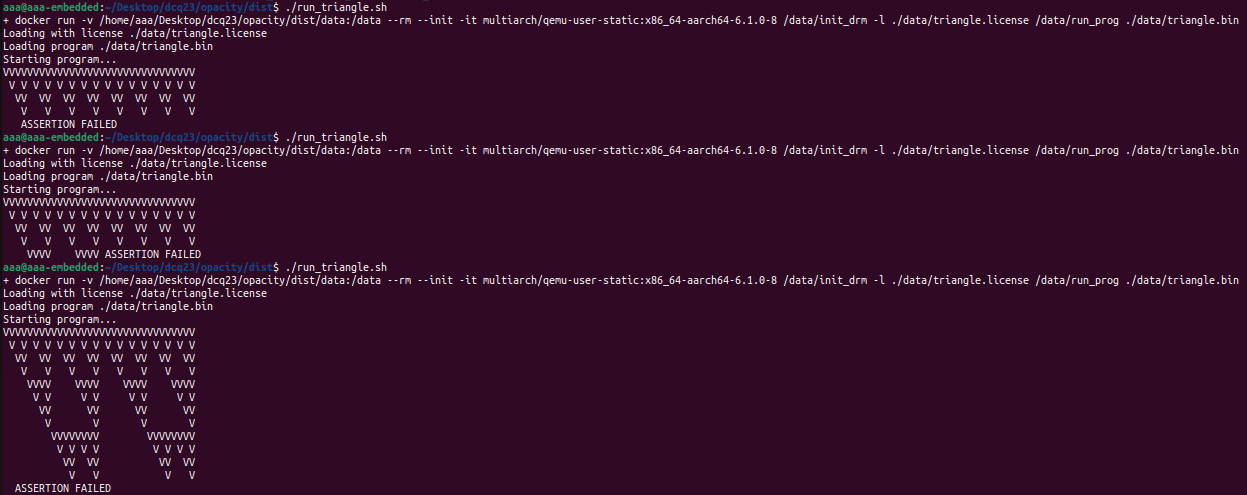
... or at least tries to, since it seems that the progam seems to hit some kind of assertion error at random points in the execution.
Author's note: I never really figured out what was triggering the assertion failure for this program. Furthermore, I didn't really see any source of randomness in its execution, so I'm actually not sure why it ended up triggering the assertion failure at seemingly random points between execution. Incidentally I've never managed to get the Sierpinski gasket to be fully printed, this is the furthest that I've ever gotten. Do drop me a mail (see home page) if you ever find out! I'd love to know!
On the other hand, we can't get the password_for_flag.bin file to run properly, as we do not have a license file for it. (The post-competition github does have the license file, if you do wish to run it locally.) It is running on the CTF servers, and if we connect we are prompted to provide an input, after which it runs for a while and then quits without producing any particular output.
Reversing init_drm
This is the first binary that is executed, taking the license file and the binary blob as arguments. Very quickly we realize that something very fishy is up. The program first opens and reads out the 16 bytes of the license file. After that, it calls sub_401D10:
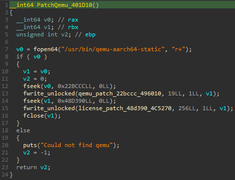
That's right! The binary searches for the docker's QEMU binary and patches it at two different places - the first with some fixed bytes and the second with the license key (with a bunch of null bytes following it). After that the init_drm binary does a little setup and then execves the patched QEMU binary to run the run_prog binary with the binary blob as its argument. This explains the extremely specific version of QEMU that the docker pulls.
The easiest way to figure out what this patch does is to dump the patched QEMU from the docker and analyze it. Jumping to the location of the first patch:
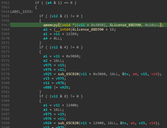
We see that the patch has landed in the middle of some large function. It appears to have modified the code to copy the bytes of our license (from the second patch) into the structure at v11. Scrolling down a little we quickly figure out where we are:
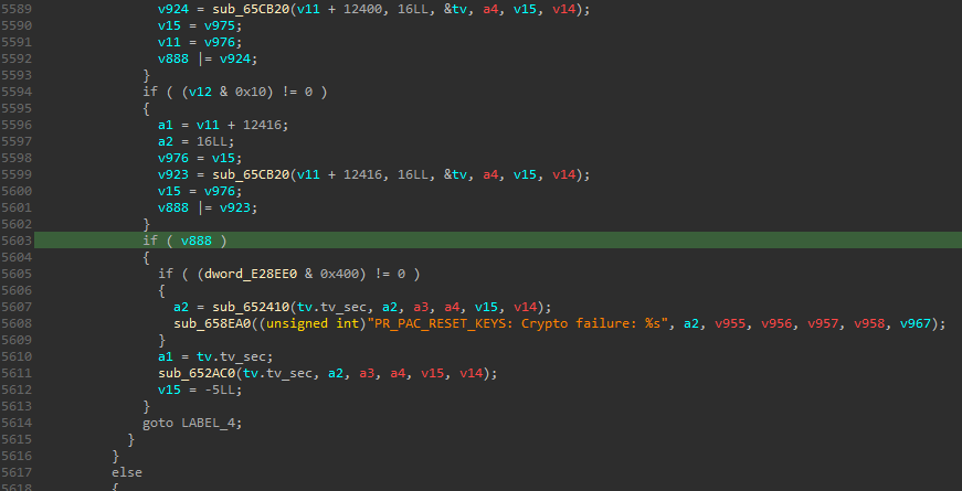
The PR_PAC_RESET_KEYS: Crypto failure message indicates that we have patched some functionality relating to ARM Pointer Authentication (PA) emulation. Looking up the error, we find that it is in the source/linux-user/syscall.c file (newer versions have refactored this functionality out into the source/linux-user/aarch64/target_prctl.h file):
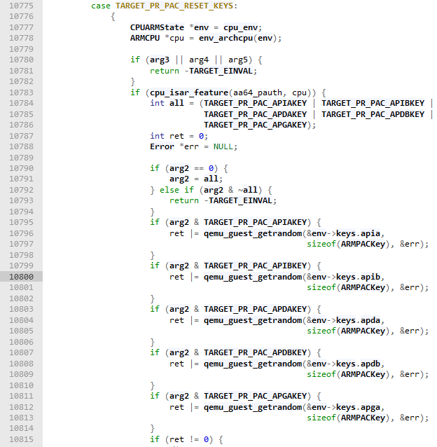
Source: https://elixir.bootlin.com/qemu/v6.1.0/source/linux-user/syscall.c#L10800
Our patch targets line 10800 of the source file, causing the PR_PAC_RESET_KEYS command of the emulated prctl syscall, which is meant to reset the thread's PA keys to random values, to instead load our 128-bit license as instruction authentication key B (PR_PAC_APIBKEY).
Aside: Pointer Authentication on ARM
ARM PA is an architectural extension introduced in ARMv8.3 for 64-bit platforms. Similar to x86-64, although addressing is done with 64-bit pointers, not all bits of the pointer are actually used for addressing. The high bits of the pointer have to be set to all 1s or 0s, otherwise the address is considered noncanonical (and generates an exception on access). PA takes advantage of this by storing extra data in these top bits of the pointer to mitigate against buffer overflow and memory corruption-type attacks.
Consider the following function epilogue/prologue code:
Prologue Epilogue PACIASPLDP x29,x30,[sp,#0x30]SUB sp, sp, #0x40ADD sp,sp,#0x40STP x29, x30, [sp,#0x30]AUTIASPADD x29, sp, #0x30RET
In the prologue, the PA instruction
PACIASPcomputes a keyed hash (using the purpose-built QARMA hash algorithm) of an instruction address stored in the link register (X30) and uses the stack pointerSP. This instruction uses the 128-bit instruction authentication key A to key the hash. Following this, the hash is truncated to fit into the unused bits of the instruction address and is stored there.This truncated hash is known as the Pointer Authentication Code (PAC) and its size is dependent on the size of the virtual addresses used and whether pointer tagging (another architectural feature) is enabled. For example, on Linux, the PAC is typically 7 bits wide assuming a typical 48 bits of addressable memory.
In the epilogue, the
AUTIASPinstruction is used to verify that the PAC of theLRandSPstored in theLRis correct. If so, the PAC is stripped from the register and is zeroed out, while on a mismatch the pointer is made noncanonical so it will raise an exception on use.All of this means that an attacker who wishes to overwrite a saved
LRpointer has to be able to guess the PAC as well, mitigating against such attacks. The inclusion of theSPin the hash makes it more difficult to reuse leaked PAC values. Incidentally, it is also possible to chain multiple of these hashes together to implement a call-stack sensitive shadow stack-like mechanism (see this paper for example).
Ultimately, what this boils down to for our challenge is that the binary has access to a keyed hash primitive which takes two values and outputs a short hash. With this understanding, we can proceed to reversing the run_prog AARCH64 executable.
Reversing run_prog
As expected, the binary calls prctl(PR_PAC_RESET_KEYS, PR_PAC_APIBKEY, 0, 0) to load our license key into instruction authentication key B shortly after starting. Poking around a little, we notice the names of several functions like run_circut (sic) or run_gate have not been stripped. This gives us a pretty good guess that this program is some sort of circuit emulator (as suggested by the challenge description). The gates parsed from the file are stored in a mmaped region at 0x0404000:
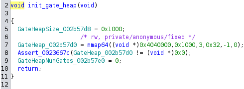
This is not too important, but most addresses are 32-bit despite running on a 64-bit system. I believe this is because it is compiled for the ilp32 ABI which restricts the integer, long and pointer types to 32-bit values. This allows the circuit representation and other structures to store the addresses in 32-bit ints instead of 64-bit.
Afer reversing, we find that the gates are loaded from the file into the gate heap. A used-by graph is built by the binary indicating which gates' outputs are connected to which gates' inputs, then the program is actually run:
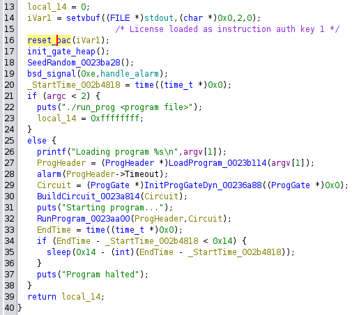
Note the cheeky little sleep call placed near the end - at the time I believed that this might have been to prevent timing attacks against e.g. a simple password match implemented by the circuit, but in hindsight I think it is meant to prevent players from bruteforcing the password for the password_for_flag.bin circuit against the challenge server (as it is indeed bruteforceable).
Eventually after a bunch of reversing goodness, I managed to write a parser for the circuit file and undertand how the circuit is executed.
Aside: Header Format
The header comprises the first 0xb0 bytes of the binary blob. It contains the following information:
- Iterations: The maximum number of timesteps the circuit will be simulated for.
- Timeout:
alarmtimeout for this circuit.io_out_gate: When the output of this gate is 1, a byte will be output fromio_out_byte[7:0].io_out_byte[7:0]: A list of 8 gates forming bits 0 to 7 of the byte to output.io_in_gate: When the output of this gate is 1, a byte will be read in from standard input intoio_in_byte[7:0]. (Technically, all input is requested at one shot and the bytes read from a buffer.)io_in_byte[7:0]: A list of 8 gates forming bits 0 to 7 of the byte read in from standard input.memtest: This gates must always be 0 after each timestep, else the program aborts.exit_pin: If this gate is 0, the program exits.flag_pin: If this gate is 1, the program reads and prints the flag from a file.memaddr[4:0]: A list of 5 gates forming bits 0 to 4 of an index into a 32-byte memory. The byte at that index will be read intomembyte[7:0]at the end of each timestep.membyte[7:0]: A list of 8 gates forming bits 0 to 8 of the byte read from RAM.mem: 32 bytes of memory.
Aside: Circuit Emulation
The following steps occur for each timestep of emulation of the circuit:
- If too many timesteps have occured, exit.
- The circuit is emulated, using the used-by graph built earlier. and a work queue. Except for clocked gates (I labelled them
REGin my parse output, pls no hate I am bad at terminology) andMEMgates which receive the byte from memory and already have their output generated at the end of the previous timestep, gates execute after all their inputs have already executed and generated outputs.- Once all the gates have executed, the various special pins noted previously are checked and the appropriate actions are carried out.
- The circuit is advanced to the next timestep, which propagates the input of each clocked gate (if any) to its output and clears the outputs of most other gates.
So in summary we have a little circuit board, with some special 'pins' for I/O, flag printing and a few other operations, as well as a small memory region. All seems well and good, so what's the catch? Well...
Opacity
... Most of the gates in the printouts are effectively opaque predicates! In other words, we do not necessarily know the output given their inputs! Let's take a look at a snippet from the parse output of the circuit:
... snip...

040403b8: REG [00000000] (0: 7910367c 1: 1b59d9a3) INIT: 1 (1b59d9a3)
040403d4: REG [00000000] (0: 376af105 1: 48bd5cc3) INIT: 0 (376af105)
040403f0: CMP 0031 != PAC([040403b8], [040403d4]) ? 4d3c418f : 48d35b5f
0404040c: CMP 001a != PAC([040403b8], [040403d4]) ? 0c91ea79 : 32781613
04040428: CMP 0055 != PAC([040403f0], [0404040c]) ? 46e05260 : 0ff04da8
04040444: CHK ASSERT([04040428] == 0ff04da8 A: False)

...snip...
We can see two REG gates (with no input, hence the [00000000]) outputting constant high and low signals respectively, represented by the ints beside them (0x1b59d9a3 representing 1 for the first, and 0x376af105 representing 0 for the second) which are the actual 'output' of the gates. The following CMP gates take the output integers from those gates, performs a PAC computation using the license key, and then checks if it is equal or not to a precomputed PAC.
For example, the gate at 0x040403f0 computes the PAC of the int output by gate 0x040403b8 as the 'instruction pointer' and the int output by gate 0x040403d4 as the modifier and checks if it is equal to 0x31. If it fails it outputs 0x4d3c418f (PAC failure generally represents a 1 bit) elese 0x48d35b5f. After going through a bunch of these gates it reaches an CHK gate which asserts the the output of gate 0x04040428 is equal to 0x0ff04da8 and aborts the program if it is not.
In run_gate we can see the magic happen:
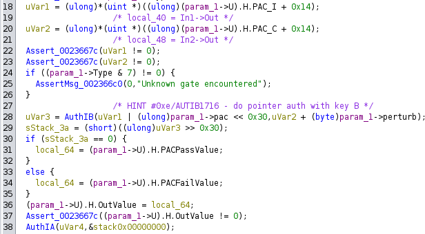
- Lines 18 and 20 read out the outputs of the two input gates to this one.
- Line 28 places the precomputed PAC value of the current gate into the top 16 bits of the value output by the first gate. The second input gate is used as the modifier, with possibly a small perturbation added to it. (This is use to avoid PAC collisions in the generation of the gate, if the same PAC is produced for different combinations of inputs.) The
AUTIB1716instruction is used to compute the PAC of these two values with our license key. - Line 29 extracts the resulting PAC bits from the output.
- Line 30 compares if the extracted bits are 0. If so, the PAC check passed and the appropriate value is written to the output of the gate, else the other value is written.
As of the time of writing, Ghidra does not compute side effects of PA instructions by default, this has to be enabled manually. See Issue #2488.
In the above snippet of circuit, not knowing exactly what comparison is made is not too big of a deal as it turns out to be a self-contained assert not used by any other parts of the circuit. However, a large majority of these gates are CMP gates. So in effect, we do not know what the gates do, but we know how they are connected to each other.
I spent a bunch of time isolating what looked like repeating patterns of gates, trying to group them by their purpose and input/output lines, and using some simple functionality that was revealed by functions in the binary, like XOR gates. To my understanding some teams were able to guess at major components of the circuit and reverse it that way(!), but unfortunately my pattern recognition skills are not quite that powerful yet. (F)
Piercing the Veil
Fortunately, we were left with a big clue that at some point I accidentally stumbled upon - that the binary actually contains multiple unreferenced functions that appeared to pertain to compiling various parts of the circuit description! For example, there was a function that seemed to end with the compilation of the triangle.bin binary:
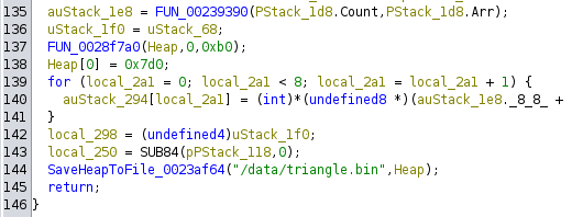
We already know that the triangle.bin binary is the same size as the password_for_flag.bin blob, but now with the parsed output we can see that both circuits are more or less identical. This function does not seem to output exactly the whole of the triangle.bin binary, but some parts of it, but this is already enough to get to work.
By reversing several unreferenced functions in the binary, we can determine what logical functionality it is trying to implement, and also determine what kind of gates are emitted in what order, as well as how they should be connected. By looking for patterns of gates connected in the right ways, we can then separate out groups of logical functionality in the binary. For example, the previous snippet can be emitted by the following bit of code, found inside the triangle.bin compilation function:

Two REG gates are emitted, the first being constant high and the second constant low, followed by an XOR of the two REG gates, and then the CHK assertion. The XOR(Gate1, Gate2) itself is compiled into three different CMP gates representing the following three operations:
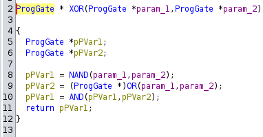
Each of the OR and AND gates compile down to a NAND gate with some NOT gates thrown in for good measure, and the NANDs become our CMP gates seen in the circuit parse output. Note that the NOT gates are compiled out of the description entirely. When a NOT gate inverts the output of the gate before it, and another gate tries to retrieve the ints corresponding to 0 and 1 for that NOT gate, the NOT gate simply inverts the result of recursively querying the gate that it itself takes as input. Hence, our XOR gets translated into three CMP gates with the appropriate connections.
... snip...

040403b8: REG [00000000] (0: 7910367c 1: 1b59d9a3) INIT: 1 (1b59d9a3)       # Constant 1
040403d4: REG [00000000] (0: 376af105 1: 48bd5cc3) INIT: 0 (376af105)       # Constant 0
040403f0: CMP 0031 != PAC([040403b8], [040403d4]) ? 4d3c418f : 48d35b5f     # 1 NAND 0
0404040c: CMP 001a != PAC([040403b8], [040403d4]) ? 0c91ea79 : 32781613     # 1 | 0
04040428: CMP 0055 != PAC([040403f0], [0404040c]) ? 46e05260 : 0ff04da8     # (1 NAND 0) AND (1 | 0)
04040444: CHK ASSERT([04040428] == 0ff04da8 A: False)                       # ASSERT(~(1 ^ 0) == 0)

...snip...
Note that in this case, there appears to have been a NOT gate inverting the input into the assert that was compiled out. Since the check must remain true, we can infer that it must be there.
In this fashion we can work out mux/demuxes, latched registers, register files, half and full adders... and finally a whole ALU - of course it had to be a tiny little CPU!
DRM-Protected Computation
This had to be expected once the circuit file had been parsed - both circuits looked very similar, but one did something completely different from the other. (I also expect that this may be part of how some people managed to reverse the circuit without finding the unreferenced functions.) All in all the CPU had the following specs:
- An immediate file (or ROM) with 4 whole 8-bit constants:
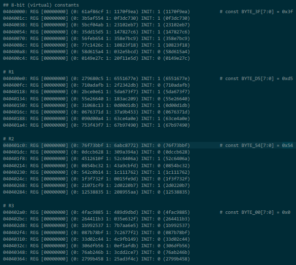
- One always-high and one always-low register
- A bunch of asserts we don't have to worry about:
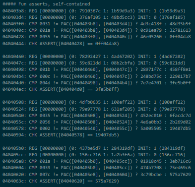
- A register file with another 4 8-bit registers - in particular
R0consisted of the I/O in byte pins, whileR3consisted of the I/O out byte pins:
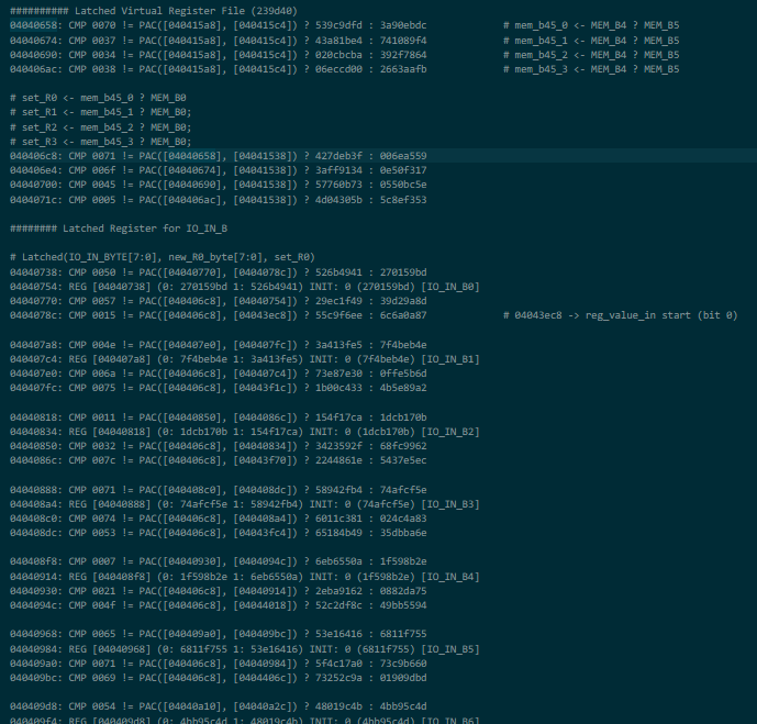
- The instruction fetch and decode logic, reading from instruction memory and selecting ALU operands:
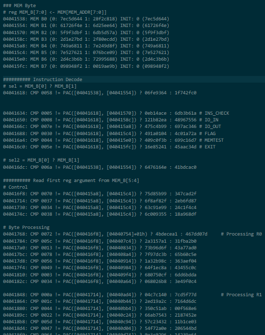
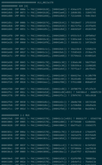
- An ALU, easily the most complicated part of this circuit, with four operations supporting all the greatest hits like
ADD,XOR,ANDand everyone's favorite,RL5(rotate left by 5 bits):
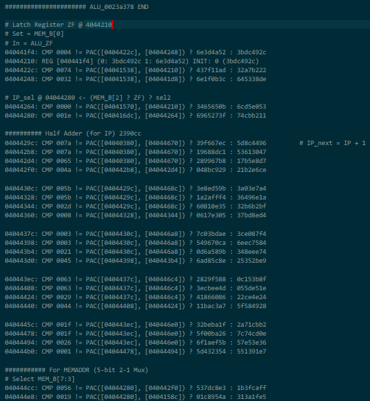
- A Zero Flag controlling a mux for the instruction pointer (i.e.
memaddr) just in case you needed to do the thing again except when you don't:
- The miscellaneous output pins noted in the header format
- A little thing that I think enforces that you begin with a specific instruction:

- And finally a whopping 32 bytes of instruction memory (in this economy??), stored in the
membytes of the header:
mem: 04 c7 26 c4 08 07 46 44 3b 08 c7 be 1b a1 f1 29 39 51 a6 4a 08 07 c6 ba 67 de ba b7 f6 ba 60 00
Armed with this information, we can finally start to decipher the opcodes for this emulated CPU. We know that operation of the ALU is controlled by bit 0 of the instruction, because it that is also the bit that controls whether the register file is written back to. Note that because of the opaque predicate, we do not know whether it has to be 0 or 1 for an ALU op.
The ALU op is selected using bits 2 and 3, the first operand with bits 4 and 5, and the second with bits 6 and 7. The first operand is always read from the register file while the second may be read from the immediate file/ROM depending on the value of bit 1. With these two facts combined we know that the ALU opcodes must be either 0b00 and 0b10, or 0b01 and 0b11.
As our main opcode appears to be 2 bits wide, that leaves us with branch instructiosn and one more operation that has to be the 'system' functions like I/O and flag printing. There must be two different kinds of branch instruction, because the 2-to-1 mux selecting the next IP also takes into account bit 2 of the opcode (bits 3-7 contain the address to jump to).
Due to the opaque predicates, I could not fully determine the encoding of the instructions so I turned to disassembling the provided programs with different possible combinations (to see if they made sense) and writing my own instructions to test their behavior in the emulator. Unfortunately, it was so close to the end that I messed up and didn't finish simply because I got the order of bits wrong in the opcode (I thought the ALU opcodes had to be 0b00 and 0b01 or 0b10 and 0b11) and was too tired to figure out what I was doing wrong :c (I did fix it a little after the competition was over though!)
In lieu of a nice circuit diagram of the CPU (I mostly worked by writing out the connections in a text file because it was small enough, along with some small mspaint diagrams), please have this official:tm: DEFCON circuit diagram, available from the Nautilus Institute github:
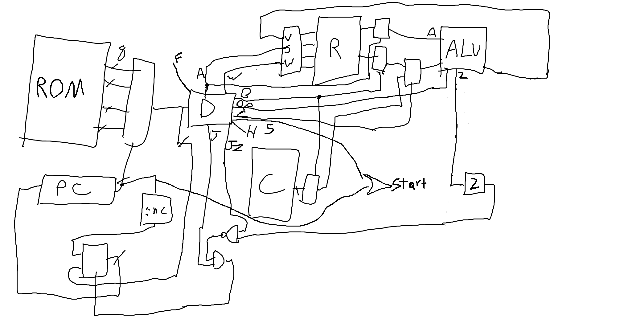
And for the curious:
Aside: CPU Instructions
Ins[1:0]:
- 0b00:
SYS- System instructions. The operation depends on which bits are set:
- Ins[2]: START instruction (
S). Must be first instruction.- Ins[3]: Read byte from stdin to
R0. (<)- Ins[4]: Print byte in
R3to stdout. (>)- Ins[5]: Print flag. (
F)- Ins[6]: Memtest (Halt). (
M)- Ins[7]: Exit. (
E)- 0b10:
B- Branch instructions.
- Ins[2] == 0: Unconditional branch. (
B)- Ins[2] == 1: Branch if zero. (
BZ)- Ins[7:3]: Branch target.
- 0b01: ALU op on two registers. The operation depends on bits 2 and 3:
- Ins[3:2] == 0b00: Rotate operand 1 left by 5 bits. (
RL5)- Ins[3:2] == 0b01: Xor operand 1 with operand 2. (
XOR)- Ins[3:2] == 0b10: Add operand 1 with operand 2. (
ADD)- Ins[3:2] == 0b11: And operand 1 with operand 2. (
AND)- Ins[5:4]: First register operand (also the destination).
- Ins[7:6]: Second register operand.
- 0b11: ALU op with first register operand and second immediate operand. Encoding is otherwise the same as the other ALU op. Immediates are referred to by
I0-I3, and can be found at the start of the circuit.
Home Stretch
All that is left is to disassemble and annotate the instructions of the password_for_flag.bin:
00 (04 00000100): SYS R0 R0 T 00	[S     ]    START
01 (c7 11000111): XOR R0 I3 T 18	[S   ME]    R0 ^= 0
02 (26 00100110): BZ  R2 R0 T 04	[S  F  ]    BZ 04           # ASSERT(R0 == 0)
03 (c4 11000100): SYS R0 R3 T 18	[S   ME]    MEMTEST
04 (08 00001000): SYS R0 R0 T 01	[ <    ]    R0 <- IN_B
05 (07 00000111): XOR R0 I0 T 00	[S     ]    R0 ^= 0x3f
06 (46 01000110): BZ  R0 R1 T 08	[S   M ]    BZ 08           # ASSERT(c[0] == '?')
07 (44 01000100): SYS R0 R1 T 08	[S   M ]    MEMTEST
08 (3b 00111011): ADD R3 I0 T 07	[ <>F  ]    R3 += 0x3f      # R3 = 0x3f
09 (08 00001000): SYS R0 R0 T 01	[ <    ]    R0 <- IN_B      # loop:
0a (c7 11000111): XOR R0 I3 T 18	[S   ME]    R0 ^= 0         #   R0 <- c[i]
0b (be 10111110): BZ  R3 R2 T 17	[S<>F E]    BZ 17           #   ASSERT(R0 != 0)
0c (1b 00011011): ADD R1 I0 T 03	[ <>   ]    R1 += 0x3f      #   R1 += 0x3f
0d (a1 10100001): RL5 R2 I2 T 14	[   F E]    R2 <<<= 5       #   R2 <<<= 5
0e (f1 11110001): RL5 R3 I3 T 1e	[  >FME]    R3 <<<= 5       #   R3 <<<= 5
0f (29 00101001): ADD R2 R0 T 05	[ < F  ]    R2 += R0        #   R2 += R0
10 (39 00111001): ADD R3 R0 T 07	[ <>F  ]    R3 += R0        #   R3 += R0
11 (51 01010001): RL5 R1 I1 T 0a	[  > M ]    R1 <<<= 5       #   R1 <<<= 5
12 (a6 10100110): BZ  R2 R2 T 14	[S  F E]    BZ 14           #   break if R1 == 0
13 (4a 01001010): B   R0 R1 T 09	[ <  M ]    B  09           #   goto loop
14 (08 00001000): SYS R0 R0 T 01	[ <    ]    R0 <- IN_B
15 (07 00000111): XOR R0 I0 T 00	[S     ]    R0 ^= 0x3f
16 (c6 11000110): BZ  R0 R3 T 18	[S   ME]    BZ 18           # ASSERT(c[n] == '?')
17 (ba 10111010): B   R3 R2 T 17	[ <>F E]    B  17
18 (67 01100111): XOR R2 I1 T 0c	[S  FM ]    R2 ^= 0xd5
19 (de 11011110): BZ  R1 R3 T 1b	[S<> ME]    BZ 1b           # ASSERT(R2 == 0xd5)
1a (ba 10111010): B   R3 R2 T 17	[ <>F E]    B  17
1b (b7 10110111): XOR R3 I2 T 16	[S >F E]    R3 ^= 0x54
1c (f6 11110110): BZ  R3 R3 T 1e	[S >FME]    BZ 1e           # ASSERT(R3 == 0x54)
1d (ba 10111010): B   R3 R2 T 17	[ <>F E]    B  17
1e (60 01100000): SYS R2 R1 T 0c	[   FM ]    FLAG
1f (00 00000000): SYS R0 R0 T 00	[      ]    NOP
In short, this binary expects a string in-between two '?' characters (MEMTEST operations are effectively 'halt and catch fire' because they raise the MEMTEST pin causing an abort), with the string in-between needing to has to a specific value. By observing when R1 becomes zero, we can determine that the string to be hashed must be 19 characters long exactly. All that is left is to brute force the hash, which is most easily done by just sending random strings at it, and we are done!
Conclusion
This was quite the fun trip, and piecing everything together was a blast! Again, I really enjoyed this challenge and the CTF as a whole. Thanks to NI for organizing everything, and to you, for reading my rambling :O
Let me know if there are any corrections/additions, typos, or just about anything cool!
Files:
- Parser and disassembler for the circuit: solve.py
- Solve for password_for_flag.bin: solvevm.py
- Annotated parse of circuit, separated into logical components: pw_notes.txt
- Extracted CPU circuit: pw_decircuited.txt
- Extracted CPU circuit with disassembly: pw_dis.txt
